


Arrow Platform
Data Preparation Guide
Overview
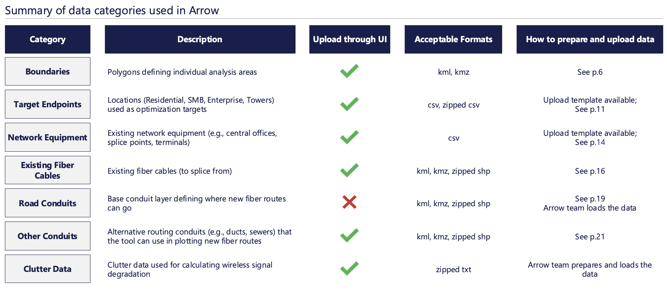
While Arrow requires numerous datasets to run optimization, most of them can be uploaded through UI
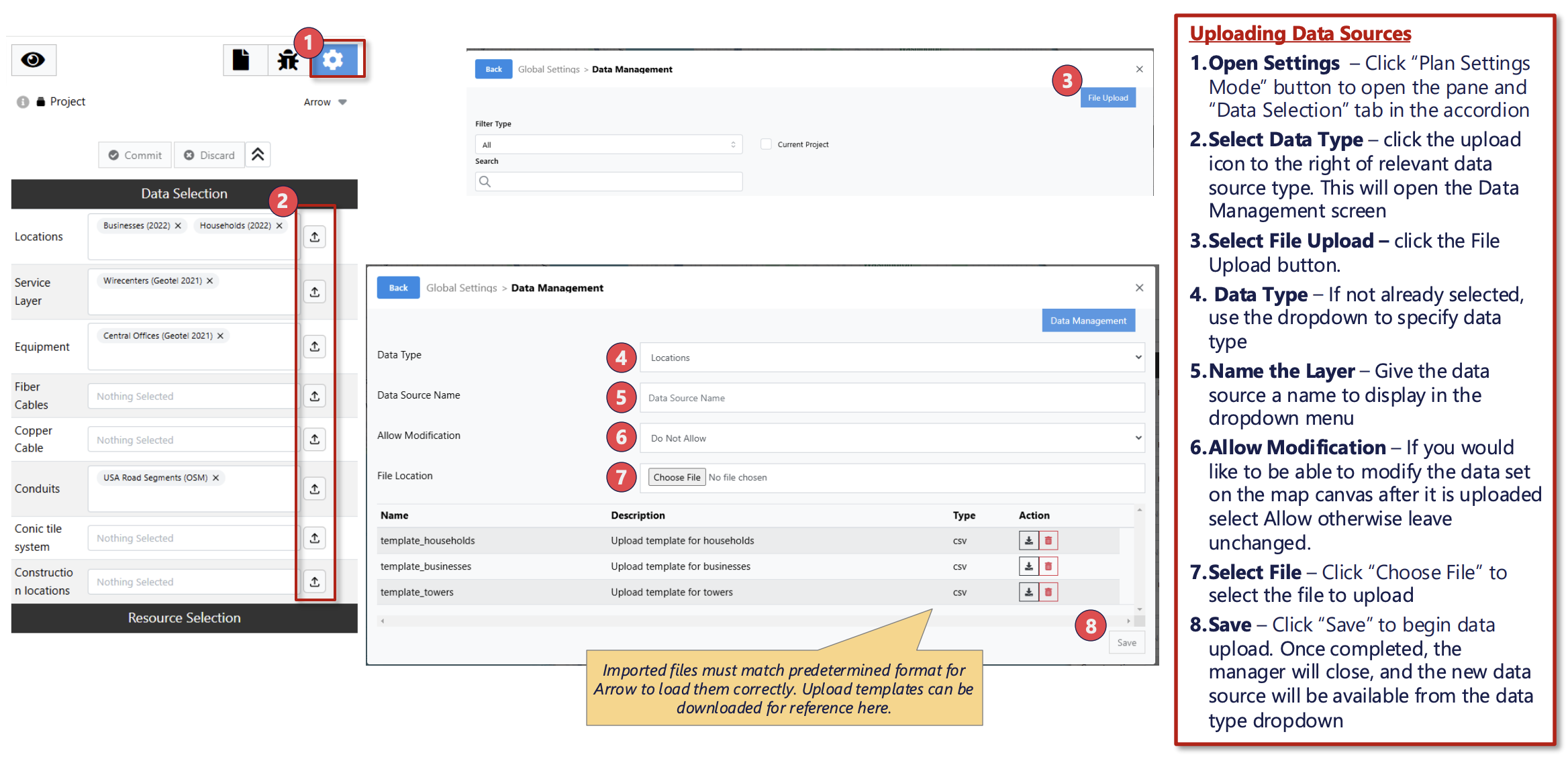
User data can be imported to Arrow via upload templates
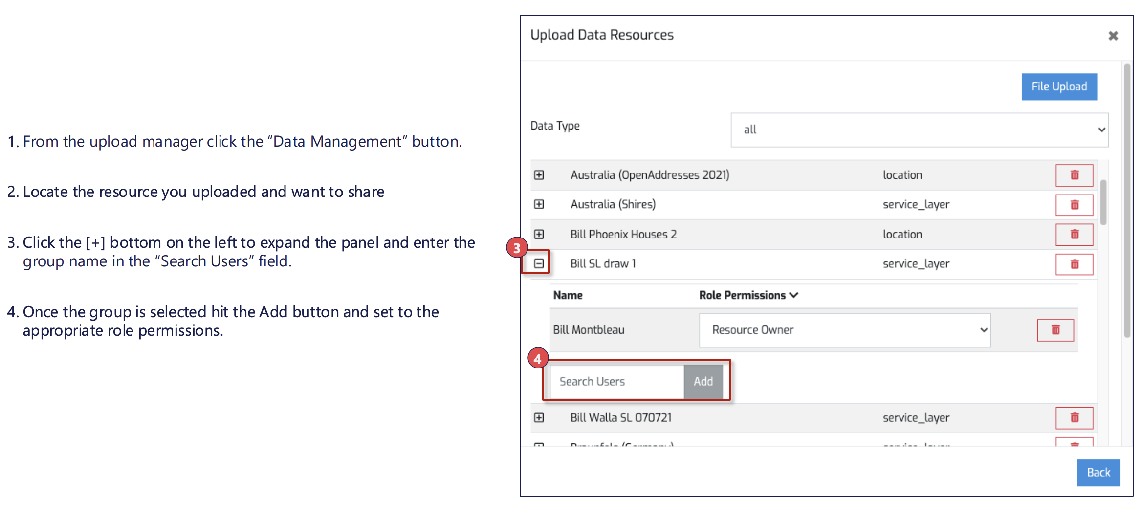
Once uploaded, individual data layers can be shared with other users and user groups
Boundaries
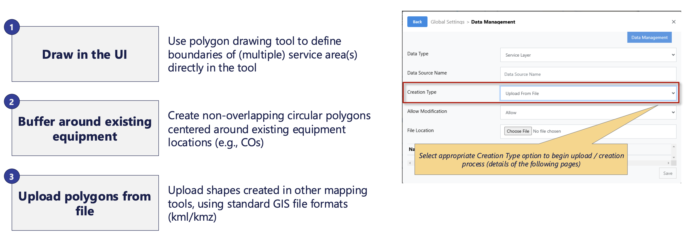
There are 3 ways to define / upload service area boundaries into Arrow
Note:
- While not strictly enforced in the tool, there is a practical limit to how large each service area can get.
- For optimal performance, aim for each service area polygon to encompass fewer than 50k target endpoints and/or 200k conduit edges (e.g., road segments)
- When analysis area gets too large, tool’s performance deteriorates and may result in plans not running to completion
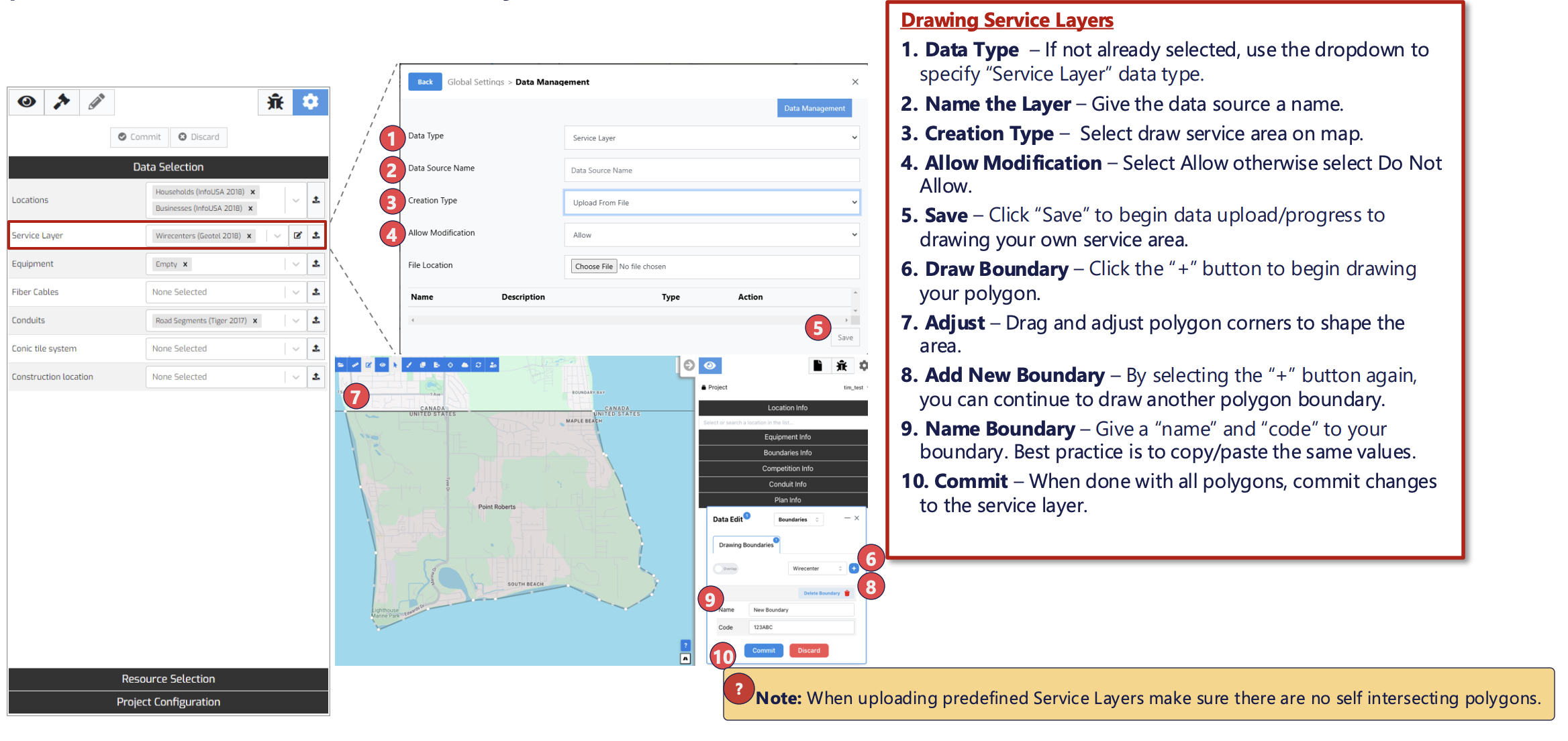
Intuitive drawing tool allows users to precisely define multiple service areas as part of the same service layer
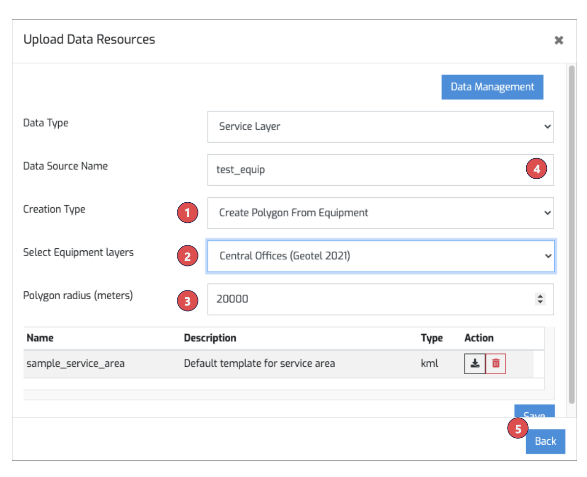
Arrow can auto-generate non-overlapping service areas by buffering around existing Central Office equipment
- Select “Create Polygon from Equipment”
- Select which equipment layer should be used to define center points of each polygon (Note: every element in that layer will be used, and only Central Office points can be used to create the new polygons)
- Specify buffer radius, in meters, for the new service areas (This defines maximum radius; in areas with more equipment elements, Arrow will create largest non-overlapping area possible)
- Don’t forget to name the service layer
- Hit “Save” (Depending on the buffer size, and number of equipment points the creation process can take up to a couple of minutes)
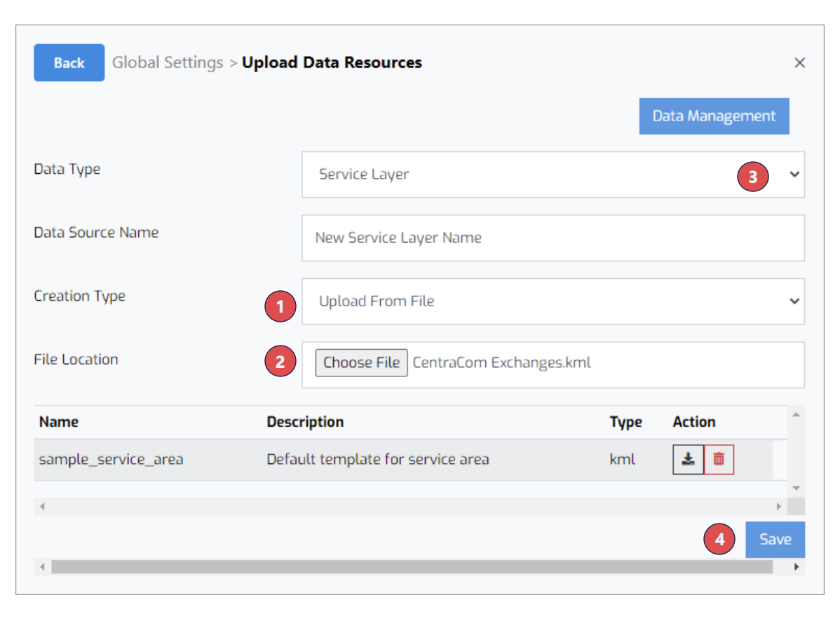
Any valid polygon generated outside of Arrow can be turned into service area by uploading kml/kmz file directly into the tool
- Select “Upload From File”
- Select file to upload from your device
- Don’t forget to name the service layer
- Hit “Save” to begin data upload process
Data Preparation & Requirements:
- Can upload kml and kmz files only
- Each feature should be defined as Polygon geometry type, not MultiPolygon (i.e. areas should be defined as contiguous shapes, no “donuts”, or carveouts for islands, etc.)
- Attribute column “name”, when available, is automatically used to name each service area. (when not available, system will auto-generate a name. Those names can later be edited using service area editing functionality)
- Coordinates should not include more than 6 digits of precision.
Target Locations
Target endpoints can be easily uploaded into Arrow using dedicated upload templates
- Location endpoints are loaded through UI using csv file only, up to 500MB in size which can be zipped
- Depending on type (residential, business, towers) list of required columns varies (see below)
- The columns need to be listed in the above order, all lowercase
- It is best to remove columns not relevant to the location type being uploaded (e.g. remove industry_id column when uploading residential locations)
- Any number of additional location attributes can be stored for future reference
- List the attributes immediately to the right of the required columns
- Column headers automatically become attribute keys
- All attributes are stored as text (e.g., scientific notation does not get converted into number; comas and decimal points become part of the text string, i.e., when uploading numbers, remove ALL formatting from columns)
- These attributes can be then visualized in the UI, and referenced in custom reports
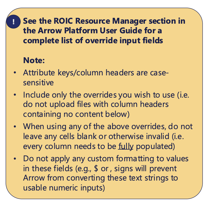
- Users also can override global ROIC and ARPU Resource Managers settings with values specific to individual locations, via a list of predefined attribute keywords
Optional fields can be provided to override global location settings and provide users with granular plan controls
BAU Case Settings:
- ROIC.BAU.START_PENETRATION – Current subscriber penetration of legacy product (0.00 – 1.00 value range)
- ROIC.BAU.MONTHLY_ARPU – ARPU for legacy product (0.0001+ value range)
- ROIC.BAU.FAIR_SHARE – Used to prescribe terminal fair share value of legacy product (0.0001 – 1.00 value range)
Plan Case Settings
- ROIC.PLAN.MONTHLY_ARPU – ARPU for the new fiber product (0.0001+ value range) (Note: Revenue fields are only used when ARPU manager is set to ‘Location Layer’ strategy)
- ROIC.PLAN.FAIR_SHARE – Used to prescribe fair share value of planned fiber network (0.0001 – 1.00 value range)
- ROIC.PLAN.SUBSIDY – Known one-time subsidy amount to be received by connecting given location
- grant_eligible – 0 or 1 (binary), to specify whether location is eligible for subsidies (when using Subsidy feature)
- comp_object_id – BDC fabric residential location id from CostQuest to enable location-level fair-share evaluation
Network Equipment
Network Equipment data can be easily uploaded into Arrow using dedicated upload template
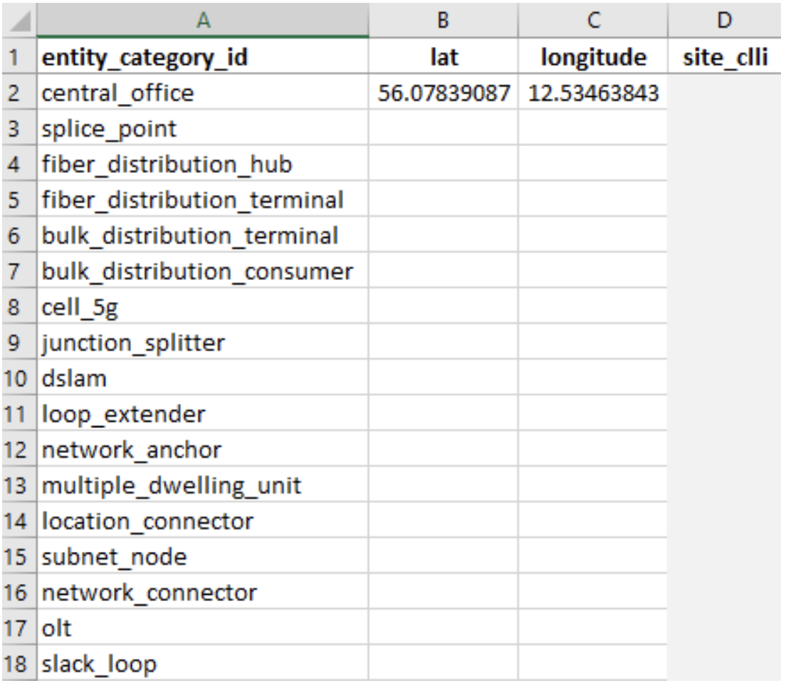
- Network equipment points are loaded through UI using csv file only, and must contain the following 3 columns:
- entity_category_id – text field – keywork defining type of equipment each point represents (see below for a list of available equipment types)
- lat – numeric field, specifying latitude of the point
- longitude – numeric field, specifying longitude of the point
- The columns need to be listed in the above order, all lowercase
- Optional attribute, site_clli (text), can be used to name each node
- If provided, this name will be made available in the UI
- Typically, only central offices and/or splice points are loaded
- Remaining equipment types are usually not needed for optimizations
- Please check in with Arrow team if you think your analysis needs to leverage one of the other equipment types (e.g. Network Connectors require additional information during upload to function correctly within the system)
Existing Fiber Cables
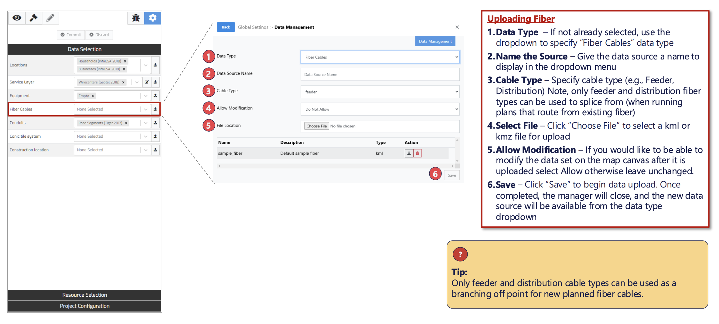
Existing fiber network infrastructure can be loaded into Arrow to use it in plans
Road Conduits
Base road layers can only be loaded directly into the database by Arrow team
Arrow team typically uses OpenStreetMap (OSM) road datasets as base roads layer.
Any collection of lines, however, can serve as primary road conduits, provided it meets the following criteria:
- Each roads dataset must include geometry column:
- only SingleLineStrings geometries are accepted
- do not include non-line elements in the file(s) to upload
- if providing csv files, geometry field needs to be stored as Well-Known Text (WKT)
- The following columns are recommended to include, if available:
- feature_sub_type – text field, equivalent of fclass in OSM datasets, allows the tool to run its routing algorithms more efficiently (faster plan runtime when using K-Means location clustering)
- construction_type – text field, (e.g. aerial vs. buried vs. underground), that allows the tool to assign precise fiber construction cost specific to this edge’s construction/placement type
- Additional attributes can be stored alongside each element, based on the need. Typical attributes include:
- osm_id – text or numeric field; unique identifier
- name – text field, e.g. street name
- Arrow team can upload data from multitude of geospatial file formats, but shp and csv files are strongly preferred.
Other Conduits
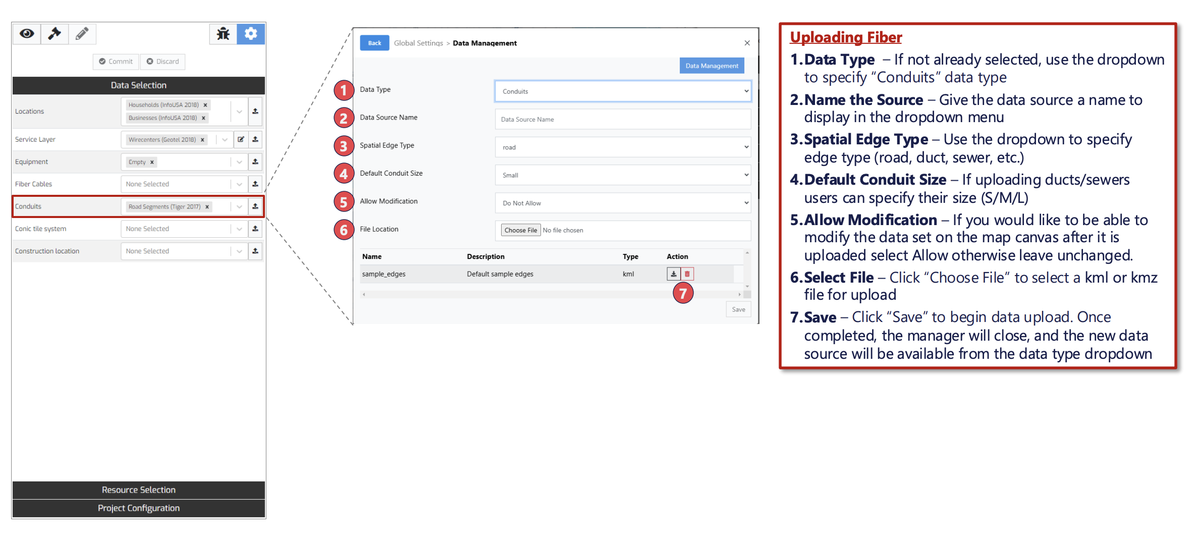
Preparation and upload of other conduits (e.g., sewers/ducts) mimics that of existing fiber cables
Other
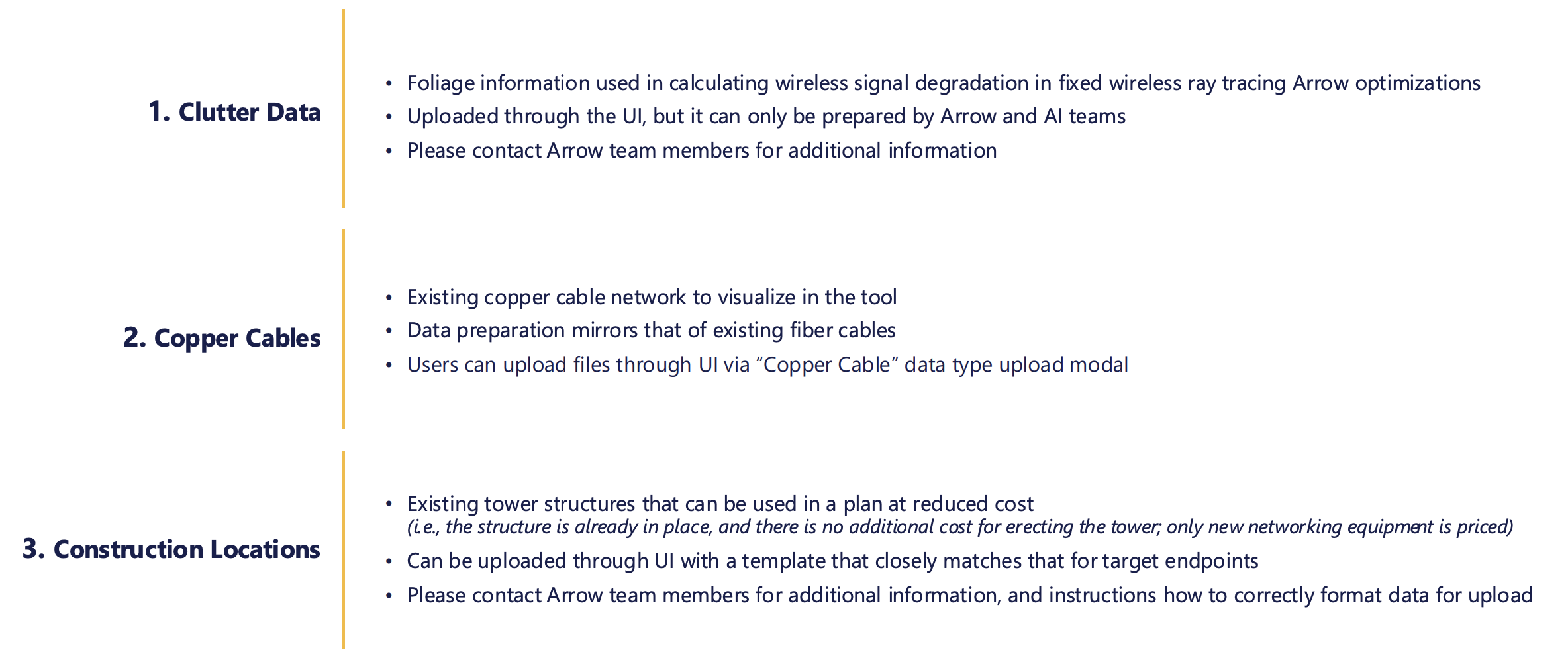
Arrow can leverage other types of data to suit additional use cases
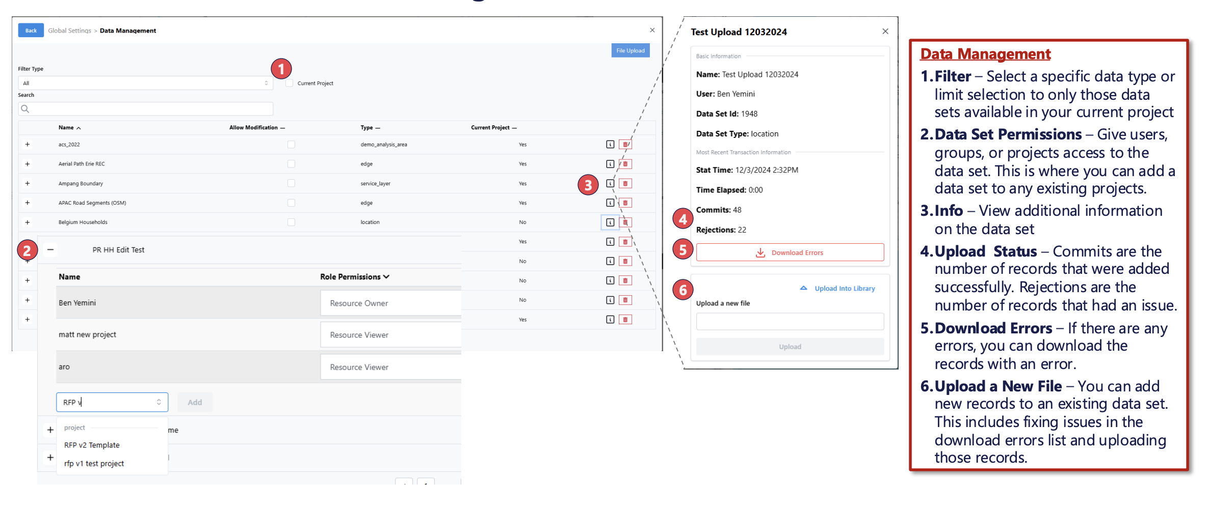
The Data Management panel enables you to manage access, add additional data and understand status of existing data sets